Vivotek AE-211 User Manual Page 4
- Page / 124
- Table of contents
- BOOKMARKS
- Camera Enclosure 1
- Specications 2
- Component Description 3
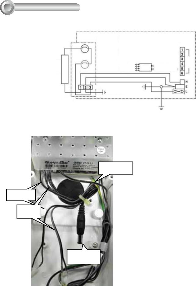
- CHASSIS EARTH 4
- COVER EARTH 4
- Installation Suggestions 5
- Camera Installation 6
- L-type wrench 9
- 2. 連接電線:僅可由合格電力技師執行電線連接工作。 10
- 請洽詢合格的技術服務人員以進行維護。 10
- 旋轉座位置及方向 11
- BR-13完整纜線管理支架 11
- 額外的攝影機及鏡頭。 12
- 將纜線從接頭移除。 12
- 2. 接腳5和6為攝影機用的DC 12V輸出 12
- 機及防護罩的使用壽命。 13
- 下圖是對FTB.1接頭的AC電力連線 13
- 12V DC輸入 16
- RJ-45乙太網路 16
- 在您調整攝影機的變焦及焦距之後, 17
- 請使用L型扳手旋緊插槽座螺絲,以關閉 17
- 2. 电器连接:只有合格的电工才能进行电器连接。 18
- 安装配置 & 尺寸 19
- 从连接头拔下电缆线。 20
- 2. 5 和 6 是摄像机的12V直流电输出插头。 20
- 下面是交流电源与FTB.1接头连接指示图。 21
- 在调整摄像机镜头的拍摄范围和焦点 25
- 后,关闭盖子并使用L型扳手收紧凹纹螺 25
- およびユーザへの指示に目を通して従う必要があります。 26
- マウント構成および寸法 27
- コンポーネント説明 27
- 設置についての提案 29
- カメラのズームおよびフォーカスを調 33
- 節してからカバーを閉じ、L型レンチを使用 33
- してソケットネジを締めて固定します。 33
- Français 35
- CHASSIS DE LA PRISE DE TERRE 36
- CAPOT DE LA PRISE DE 36
- Installation de la Caméra 38
- Especicaciones 42
- Direcciones y 43
- Soporte de gestión completa 43
- CHASIS TIERRA 44
- CUBIERTA TIERRA 44
- (Unidad de suministro 45
- Instalación de la cámara 46
- Technische Daten 50
- Komponentenbeschreibung 51
- GEHÄUSE ERDUNG 52
- ABDECKUNG ERDUNG 52
- Installationshinweise 53
- Kamerainstallation 54
- Especicações 58
- Descrição do Componente 59
- ARMAÇÃO TERRA 60
- COBERTURA TERRA 60
- Sugestões de Instalação 61
- Instalação de Câmera 62
- Português 63
- Speciche tecniche 66
- Descrizione componenti 67
- TERRA CHASSIS 68
- COPERCHIO TERRA 68
- Consigli di installazione 69
- Installazione videocamera 70
- Italiano 71
- Teknik Özellikler 74
- Bileşen Açıklaması 75
- Kurulum Önerileri 77
- Kamera Kurulumu 78
- Kameranın yakınlaştırma ve 81
- Specykacje 82
- Opis elementów 83
- PODSTAWA MONTAŻOWA ZIEMII 84
- POKRYWA ZIEMII 84
- Sugestie dotyczące instalacji 85
- Instalacja kamery 86
- Спецификация 90
- Описание элементов 91
- Рекомендации по монтажу 93
- Монтаж камеры 94
- После регулировки масштаба 97
- Technické údaje 98
- Montáž, kongurace a rozměry 99
- Popis komponentů 99
- SPODNÍ ČÁST 100
- Doporučení k instalaci 101
- Instalace kamery 102
- AC Input 104
- Specikationer 106
- Beskrivning av komponent 107
- CHASSI JORDAD 108
- LOCKET JORDAD 108
- Förslag till installation 109
- Kamera installation 110
- RJ-45 Ethernet 112
- AC ineffekt 112
- BR-13 115
- ﺔﻴﺿرأ ﻞﻜﻴﻬﻟا 116
- 2 118
- 3 118
- 5 119
- 9 120
- 11 121
- 121
- L 121
- User's Manual 122
- E: [email protected] 124
© 2020, manymanuals.com. All rights reserved. | 0.894 s |
 Manymanuals.com
 Manymanuals.de
 Manymanuals.fr
 Manymanuals.it
 Manymanuals.pl
 Manymanuals.cz
 Manymanuals.es
 Manymanuals-pt.com
Comments to this Manuals