Vivotek VS3102 Installation Guide Page 11
- Page / 83
- Table of contents
- BOOKMARKS
- Before You Use This Product 3
- Table of Contents 4
- Package Contents 8
- Physical Description 9
- Rear Panel 10
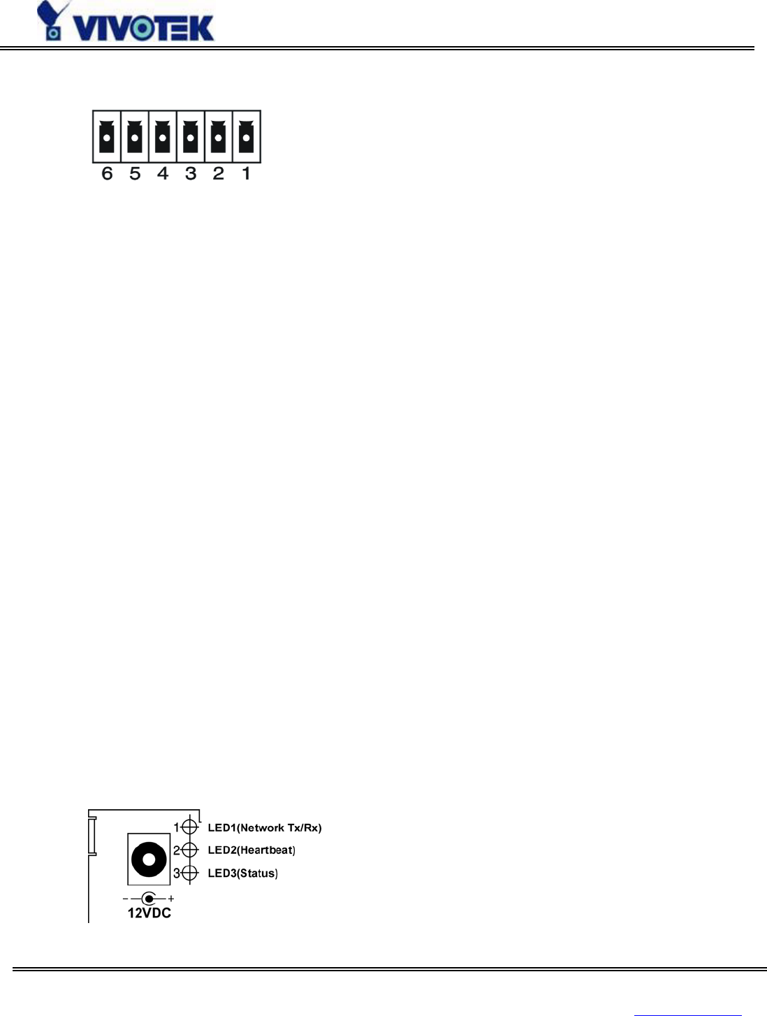
- General I/O terminal block 11
- Status LEDs 11
- Restore button 12
- Power adapter 13
- Installation 14
- Ethernet Environment 15
- Power on 16
- Modem Environment 18
- Cable Connection 19
- Power On 19
- Software Installation 20
- Setup a New Connection 23
- How to Use 30
- Authentication 31
- Installing plug-in 32
- Primary User’s Capability 33
- Client Setting 35
- System configuration 37
- System parameters 38
- User group administration 40
- Network settings 41
- UPnP and DDNS Settings 46
- Video codec parameters 48
- Motion detection 51
- PTZ camera configuration 52
- Modem and dialup settings 56
- Application settings 58
- Homepage layout settings 60
- Advanced functions 61
- Customizing homepage images 62
- Viewing system log 63
- Software revision upgrade 63
- System core debugging 64
- Reset system 66
- Restart system 68
- Page URL 68
- System resource URL 70
- System configuration URL 70
- Security configuration URL 71
- Network configuration URL 71
- Video configuration URL 72
- Modem configuration URL 75
- Appendix 78
- C. Technical specifications 82
- Liability 83
Related products and manuals for Video servers/encoders Vivotek VS3102
 (96 pages)
© 2020, manymanuals.com. All rights reserved. | 0.990 s |
 Manymanuals.com
 Manymanuals.de
 Manymanuals.fr
 Manymanuals.it
 Manymanuals.pl
 Manymanuals.cz
 Manymanuals.es
 Manymanuals-pt.com
Comments to this Manuals