Vivotek PT3113 User Manual Page 7
- Page / 66
- Table of contents
- BOOKMARKS
- Before You Use This Product 2
- Table of Contents 3
- Package Contents 6
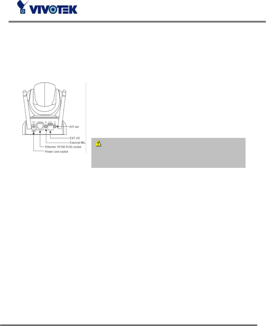
- Installation 7
- To install in wireless LAN 8
- Software Installation 9
- Check Network Settings 12
- How to Use 13
- Installing Plug-in 14
- Primary User’s Capabilities 15
- The Configuration: 16
- The camera view: 16
- Client Settings 17
- Administrator’s Capabilities 19
- Only Quality Images Will Do 20
- Software Revision Upgrade 30
- Definitions in Configuration 31
- System Parameters 32
- User Group Administration 33
- Network Settings 34
- Streaming 35
- WLAN Configuration 35
- Mail & FTP 37
- Video Codec Parameters 39
- Motion Detection 41
- Application Setup 42
- Sequential Operation 43
- Camera Control 44
- Preset Function Area 45
- UPnP and DDNS Settings 46
- Remote Controller 47
- Viewing System Log 48
- Viewing System Parameters 48
- Factory Default 48
- Appendix 49
- Drive the Digital Output 53
- Restart System 54
- Page URL 55
- System Resource URL 55
- System Configuration URL 56
- Security Configuration URL 57
- Network Configuration URL 57
- Camera Control URL 62
- D. Technical Specifications 65
- Liability 66
© 2020, manymanuals.com. All rights reserved. | 2.229 s |
 Manymanuals.com
 Manymanuals.de
 Manymanuals.fr
 Manymanuals.it
 Manymanuals.pl
 Manymanuals.cz
 Manymanuals.es
 Manymanuals-pt.com
Comments to this Manuals