Vivotek MD8531H User Manual Page 11
- Page / 207
- Table of contents
- BOOKMARKS
- User’s Manual 1
- 2 - User's Manual 2
- Overview 4
- Read Before Use 5
- Package Contents 5
- Physical Description 6
- DI/DO Diagram 7
- Dimensions 7
- Installation 8
- Rubber Seal Plug 9
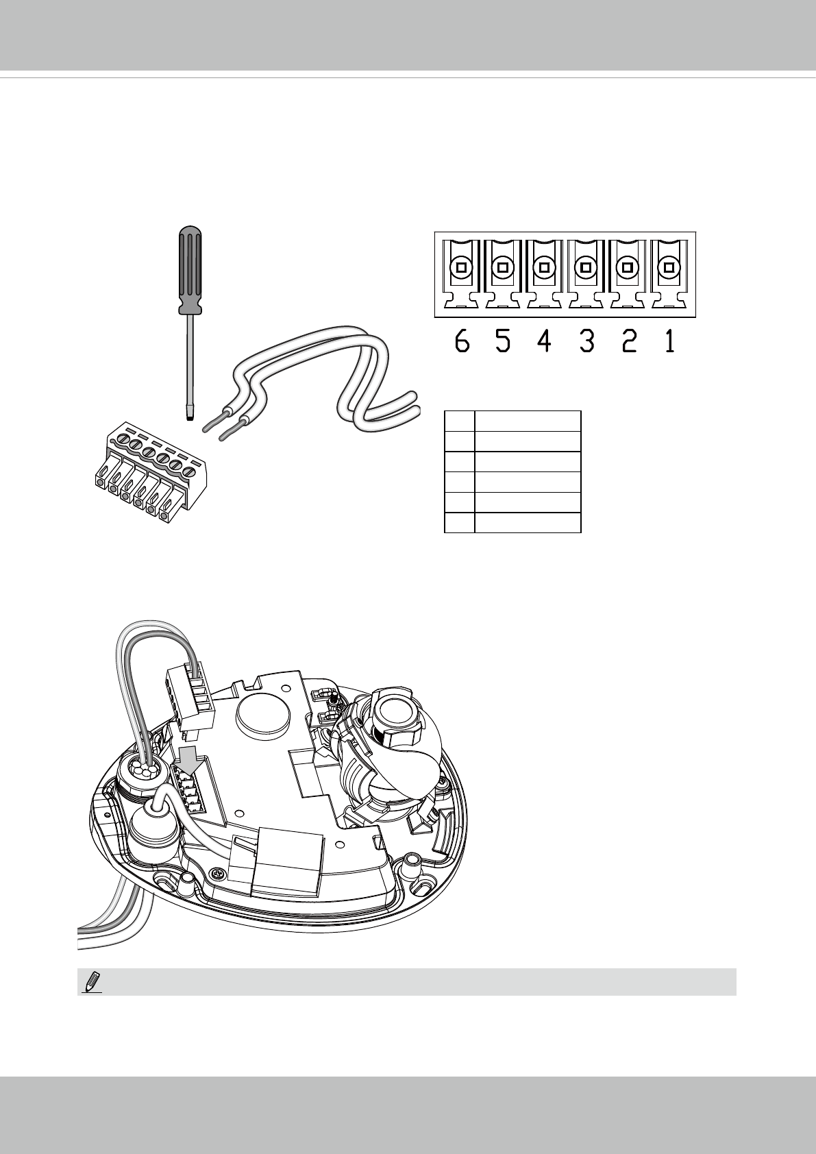
- 3.2 Connecting IO cables: 10
- User's Manual - 11 11
- 3.3 Ceiling Mount 12
- Network Deployment 13
- 14 - User's Manual 14
- User's Manual - 15 15
- 0002D1730202 16
- Ready to Use 17
- Adjusting the Lens 18
- Completion 19
- Accessing the Network Camera 20
- User's Manual - 21 21
- 22 - User's Manual 22
- Using RTSP Players 23
- 24 - User's Manual 24
- User's Manual - 25 25
- Main Page 26
- The viewing region of 27
- The largest frame size 27
- Live Video Window 28
- User's Manual - 29 29
- Video Control Buttons 30
- Client Settings 31
- Date and time suffix 32
- File name prefix 32
- Joystick Settings 33
- Enable Joystick 33
- Buttons Conguration 34
- Conguration 35
- System > General settings 36
- System time 37
- System > Homepage layout 38
- Theme Options 39
- 40 - User's Manual 40
- System > Logs 41
- Internet 42
- System > Parameters 43
- System > Maintenance 44
- General settings > Restore 45
- Import/Export les 45
- 46 - User's Manual 46
- User's Manual - 47 47
- Media > Image 48
- MirrorNormal Flip Rotate 90° 49
- 50 - User's Manual 50
- Image settings 51
- Exposure 52
- AE (Automatic Exposure) 53
- 54 - User's Manual 54
- Media > Video 55
- 56 - User's Manual 56
- Region of Interest 57
- (Viewing Region) 57
- Output Frame Size 57
- 58 - User's Manual 58
- User's Manual - 59 59
- 60 - User's Manual 60
- Media > Audio 61
- Network > General settings 62
- User's Manual - 63 63
- 64 - User's Manual 64
- From the Internet In LAN 65
- 66 - User's Manual 66
- User's Manual - 67 67
- 68 - User's Manual 68
- HTTP streaming 69
- RTSP Streaming 70
- Video 16:38:01 2014/1/25 71
- 72 - User's Manual 72
- Network > DDNS 73
- 73
- Manual setup 74
- ■ Safe100.net 74
- ■ CustomSafe100 75
- DDNS providers: 75
- 76 - User's Manual 76
- QoS/DSCP (the DiffServ model) 77
- Network > SNMP 78
- Security > User Account 79
- Account management 80
- Security > HTTPS 81
- 82 - User's Manual 82
- User's Manual - 83 83
- 84 - User's Manual 84
- User's Manual - 85 85
- 86 - User's Manual 86
- Note that 87
- Security > Access List 88
- User's Manual - 89 89
- Administrator IP address 90
- Security > IEEE 802.1X 91
- 92 - User's Manual 92
- PTZ > PTZ settings 93
- Home page in E-PTZ Mode 94
- 2011/03/10 17:08:56 95
- 96 - User's Manual 96
- Event > Event settings 97
- 2. Trigger 98
- User's Manual - 99 99
- 3. Action 100
- Add server 101
- 102 - User's Manual 102
- User's Manual - 103 103
- 20130820 104
- 20130821 104
- 20130822 104
- 2013/08/20 105
- Add media 106
- Trigger Activation 107
- Video_20130813_100341 108
- User's Manual - 109 109
- Customized Script 110
- 2014/1/5 14:39:12 111
- Percentage = 30% 112
- User's Manual - 113 113
- Applications > DI and DO 114
- User's Manual - 115 115
- 116 - User's Manual 116
- User's Manual - 117 117
- Platform) 118
- User's Manual - 119 119
- Recording Settings 120
- Activity Adaptive Streaming 121
- Continuous recording 121
- 122 - User's Manual 122
- User's Manual - 123 123
- 20131010 124
- 20131011 124
- 20131012 124
- User's Manual - 125 125
- 126 - User's Manual 126
- 2014/1/20 10:43:06 127
- Click to switch 128
- Appendix 129
- 4. Security Level 130
- [<parameter pair>] 133
- 7.1 system 134
- 7.1.1 system.info 138
- 7.2 status 139
- 7.5 security 140
- 7.6 network 141
- 7.6.1 802.1x 142
- 7.6.2 QOS 143
- 7.6.3 IPV6 143
- 7.6.4 FTP 144
- 7.6.5 HTTP 144
- 7.6.6 HTTPS port 145
- 7.6.7 RTSP 145
- 7.6.7.1 RTSP multicast 146
- 7.7 IP Filter 147
- 7.8 Video input 148
- 7.9 Video input preview 157
- 7.12 Audio input per channel 161
- 7.15 DDNS 163
- 7.16 Express link 164
- 7.17 UPnP presentation 164
- 7.18 UPnP port forwarding 164
- 7.19 System log 165
- 7.20 UART control 165
- 7.21 SNMP 166
- 7.23 Privacy mask 168
- 7.24 Capability 168
- 7.28 Customized event script 178
- 7.29 Event setting 178
- 7.32 Recording 183
- 7.33 HTTPS 185
- 7.35 Region of interest 186
- 7.36 ePTZ setting 187
- User's Manual - 189 189
- 8. Useful Functions 190
- Capture Single Snapshot 192
- Account Management 192
- System Logs 193
- Upgrade Firmware 194
- IP Filtering 197
- IP Filtering for ONVIF 199
- Get SDP of Streams 200
- Open the Network Stream 201
- User's Manual - 205 205
- Technology License Notice 206
- User's Manual - 207 207
Related products and manuals for Security cameras Vivotek MD8531H
 (2 pages)
 (25 pages)
(220 pages)
(251 pages)
(216 pages)
(149 pages)
(19 pages)
(13 pages)
(25 pages)
(220 pages)
(251 pages)
(216 pages)
(149 pages)
(19 pages)
(13 pages)
 (2 pages)
 (126 pages)
© 2020, manymanuals.com. All rights reserved. | 0.071 s |
 Manymanuals.com
 Manymanuals.de
 Manymanuals.fr
 Manymanuals.it
 Manymanuals.pl
 Manymanuals.cz
 Manymanuals.es
 Manymanuals-pt.com
Comments to this Manuals